Product Overview
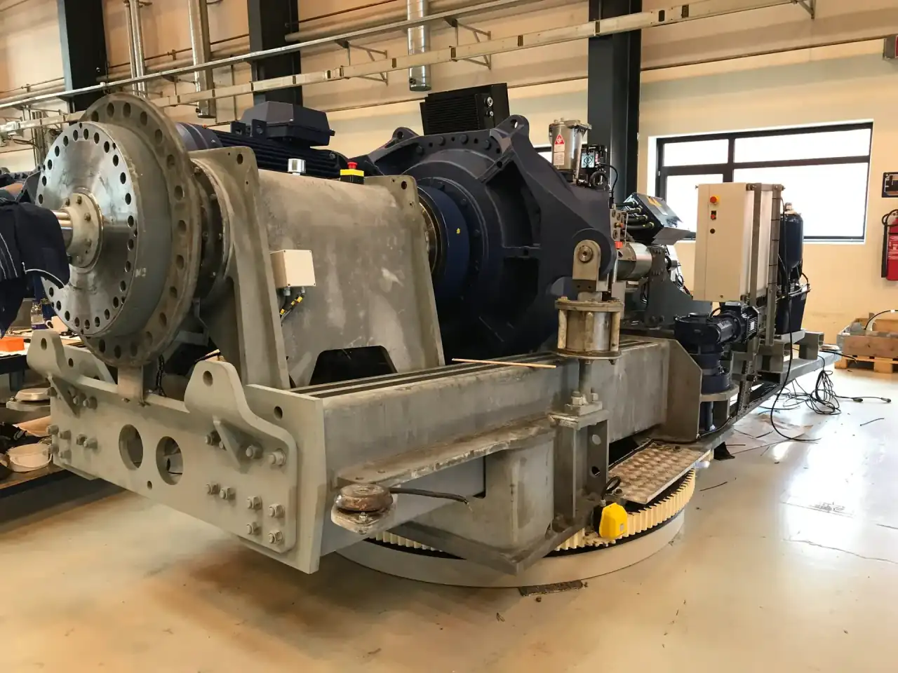
Nacelle frames and bedplates serve as the primary structural backbone for wind turbine drivetrains, supporting the main shaft, gearbox, generator, and yaw system under extreme cyclic loads. These heavy weldments are fabricated from high-strength structural steel plates ranging from 30 mm to 150 mm thickness, with single-piece capacities up to 80 tons. The fabrication process begins with precision plasma or laser cutting of plates to EN 1090-2 EXC4 execution class requirements, followed by multi-pass submerged arc welding (SAW) and flux-cored arc welding (FCAW) using filler metals certified to AWS A5.29 and EN ISO 17632. Each weld joint is designed to withstand fatigue loads exceeding 10^7 cycles per IEC 61400-1 design standards, with full penetration butt welds and partial penetration T-joints verified through 100% ultrasonic testing (UT) per EN ISO 17640 and magnetic particle testing (MT) per EN ISO 17638.
Post-Weld Stress Relief Heat Treatment
Post-weld stress relief heat treatment (PWHT) is mandatory for all nacelle frame and bedplate assemblies to eliminate residual stresses from welding and ensure dimensional stability over the turbine's 20-year design life. PWHT is performed in a programmable gas-fired furnace with temperature control per EN 10052, typically holding at 580°C to 620°C for one hour per 25 mm of thickness, followed by controlled cooling at a maximum rate of 50°C per hour to prevent re-hardening or distortion. For thick-section joints exceeding 80 mm, intermediate stress relief is applied during multi-pass welding to maintain interpass temperatures between 150°C and 250°C, as specified in EN 1011-2. This thermal treatment reduces peak residual stresses below 30% of the material yield strength, verified through hole-drilling strain gauge measurements per ASTM E837, ensuring the bedplate maintains its ±0.05 mm machining tolerance on critical bearing and gearbox interfaces after years of operation.
CNC Machining and Surface Protection
CNC machining of nacelle frame interfaces is performed on a 6-meter x 4-meter x 2-meter gantry mill with Heidenhain TNC 640 control, achieving positional accuracy of ±0.02 mm and surface finish Ra 1.6 μm on all bearing seats and gearbox mounting pads. The main shaft bearing housings are bored to H7 tolerance per ISO 286-2, with concentricity held within 0.03 mm across the full span of the bedplate. Gearbox mounting flanges are machined flat to 0.05 mm per meter, with bolt hole patterns positioned to ±0.1 mm relative to the turbine's pitch circle diameter. All machined surfaces are protected with a two-coat epoxy primer system meeting ISO 12944-4 C5-M corrosion protection requirements, with dry film thickness of 240 μm minimum. Integrated lifting lugs and transport brackets are designed to DNV-GL-ST-0378 standards, with a safety factor of 4:1 against yield, enabling safe handling during assembly and offshore installation.
Applications & Industries
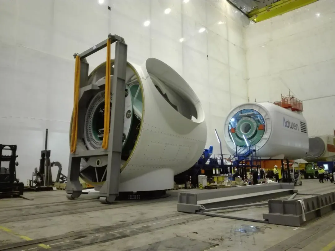
Nacelle frames and bedplates fabricated by Leading Top Union are deployed across onshore and offshore wind turbine platforms rated from 3 MW to 15 MW, serving major OEMs and EPC contractors in the renewable energy sector. For offshore wind farms in the North Sea and Baltic Sea, bedplates are designed to withstand extreme wave loads and 50-year storm conditions per DNV-OS-J101, with fatigue life calculations based on S-N curves from EN 1993-1-9. A typical 8 MW offshore turbine nacelle frame weighs 45 to 65 tons, supporting a drivetrain that transmits 12,000 kNm of torque at rated wind speeds of 12 m/s. The bedplate's yaw bearing interface must maintain alignment within 0.1 degrees over the turbine's operational life, requiring machining tolerances of ±0.05 mm on the 4-meter diameter yaw ring mounting surface. These assemblies are subjected to 100% NDT including phased array ultrasonic testing (PAUT) per ASTM E2491 for detection of planar defects down to 2 mm in length.
Marine Propulsion Applications
Beyond wind energy, heavy fabrication capabilities support nacelle frame and bedplate applications in marine propulsion systems, where the structural demands mirror those of wind turbines. For azimuth thrusters on dynamic positioning vessels, bedplates are fabricated from NV E36 or DH36 shipbuilding steel per DNV rules, with plate thicknesses up to 120 mm and single-piece weights of 60 tons. These components must resist torsional vibrations from diesel-electric drives operating at 600 to 1200 RPM, requiring the PWHT process to maintain flatness within 0.5 mm over 5 meters after machining. The gearbox mounting interfaces are bored to H6 tolerance with surface finish Ra 0.8 μm, ensuring oil film integrity for hydrodynamic bearings. Each marine bedplate undergoes 100% radiographic testing (RT) per EN ISO 17636-1 on all full-penetration welds, with acceptance criteria per EN ISO 5817 level B, the strictest quality level for welded joints in critical safety applications.
Mining and Mineral Processing Frames
In the mining and mineral processing industry, nacelle-style frames are used for large grinding mill drives and conveyor head pulleys, where the structural loads exceed 500 tons of static weight plus dynamic impact forces. Bedplates for SAG mill drives are fabricated from AR400 or AR500 abrasion-resistant steel with thicknesses up to 150 mm, designed to ASME BTH-1 for below-the-hook lifting devices. The main bearing housings are machined to accommodate spherical roller bearings with bore diameters up to 1.2 meters, held to IT6 tolerance per ISO 286-2. These assemblies require post-weld heat treatment at 550°C to 600°C for stress relief, followed by controlled cooling to prevent hydrogen-induced cracking in thick sections. Each weld is inspected using time-of-flight diffraction (TOFD) ultrasonic testing per EN ISO 15626, capable of detecting through-wall flaws as small as 1 mm in plates up to 200 mm thick. The finished bedplate is coated with a three-layer epoxy-polyurethane system per ISO 12944-5 for corrosion resistance in acidic mine environments.
Why Choose Leading Top Union for Nacelle Frame & Bedplate Fabrication
Quality Management and Welding Certification
Leading Top Union's Suzhou facility operates under a comprehensive quality management system certified to ISO 3834-2 for welding, EN 1090-2 EXC4 for structural steel execution, and AWS D1.1 for structural welding code compliance. Welding procedures are qualified to EN ISO 15614-1 for all plate thicknesses up to 150 mm, covering SAW, FCAW, and gas metal arc welding (GMAW) processes with filler metals matched to parent material strengths from S355 to S690QL. A dedicated NDT laboratory is maintained with certified Level III inspectors per EN ISO 9712, capable of performing UT, MT, RT, and PAUT on all weld categories. For critical main shaft bearing welds, 100% phased array ultrasonic testing is applied with automated scanning systems that record full volumetric data for traceability, meeting the requirements of DNV-GL-ST-0361 for offshore wind turbine components.
Engineering Support and Process Simulation
The engineering team provides full design-for-manufacturing support, including finite element analysis (FEA) per EN 1993-1-5 for plate buckling and EN 1993-1-8 for welded joint design. The PWHT cycle is simulated using computational thermal analysis to predict distortion and residual stress distribution, optimizing fixture placement and weld sequencing to maintain final machining allowances within 3 mm on 80-ton assemblies. For each nacelle frame, a welding sequence plan is generated that balances heat input across the structure, using preheat temperatures calculated per EN 1011-2 based on carbon equivalent values (CEV) up to 0.45%. The CNC machining center is equipped with on-machine probing that measures critical interfaces in-process, compensating for thermal growth and tool wear to hold ±0.05 mm tolerances without secondary operations. All dimensional data is recorded in a digital twin for full traceability from raw plate to finished assembly.
Logistics and Project Management
Logistics and project management are integrated into the fabrication process, with each nacelle frame and bedplate designed with integrated lifting lugs, transport saddles, and corrosion-protected surfaces for global shipment. Coordination with third-party inspection agencies such as DNV, Lloyd's Register, or Bureau Veritas is provided for witness and hold points, ensuring compliance with project-specific requirements for offshore wind or marine applications. The facility's 80-ton overhead crane capacity and 12-meter-wide assembly bays allow handling of single-piece weldments that fit within standard shipping containers or flat-rack configurations. With a typical lead time of 12 to 16 weeks from material procurement to final inspection, just-in-time delivery schedules for turbine assembly lines are supported. Contact our technical sales team at info@leadingtopunion.com with your nacelle frame specifications, including main bearing bore diameters, gearbox interface dimensions, and required execution class, for a detailed fabrication proposal with full NDT and certification documentation.